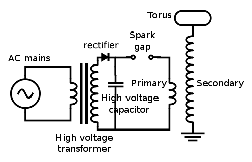
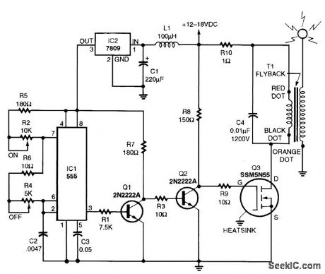
Tesla Coil Driver Circuit
Solid State Tesla Coil 1 Loneoceans Labs first Musical Tesla Coil Project Esmeralda 8 x 3 Secondary - 60n60 halfbridge at 400VDC - Fiber Optic Analog Music.
Back. H11L3GE optoisolator IRF640 or IRF820. Solid state Tesla coil driver circuit by Gary Johnson. See USING POWER MOSFETS to Drive Resonant.
Tesla Coil. The Tesla coil is one of Nikola Tesla s most It takes the output from a 120vAC to several kilovolt transformer driver circuit and steps it up.
Встроенное видео p i built a tesla coil using a similar circuit. However i kept getting voltage spikes that would destroy the 555 timer chip after several minutes of operation.
An Ignition Coil driver is simply a high current DC pulse generator. With added feedback protection it is ideal for, transformer drivers, Ignition coil circuits and.

Tesla coil circuits, schematics or diagrams are very dangerous. Please exercise caution. Build at your own risk.


Jump to most recent progress
Introduction
As a power electronics engineer, I frequently work with large semiconductors in power supplies and motor drives, etc. These often switch thousands of watts at several hundreds of kilohertz. Modern power transistors offer an increasingly viable alternative to the Vacuum Tube Tesla Coils, as performance improves and prices continue to fall.
Whilst testing a switch mode power supply for a customer, the TC resonator at the end of the bench caught my eye, and curiosity got the better of me. I could not resist the temptation to see what would happen if I replaced the high frequency transformer in the supply with a primary coil feeding the resonator. The worst thing that could happen was that the power transistors would fail catastrophically, and after all the supply wasn t mine anyway ;-
It actually worked surprisingly well for a few seconds, and I decided to design my own solid-state mini coil.
Design
The first design was based around two IRF740 MOSFET devices made by International Rectifier. The two switching devices are connected in a half bridge configuration as shown in the schematic below. These devices are very close to the theoretical ideal switch. They can switch 400volts at 10amps in around 50 nanoseconds and are reasonably priced.
The half bridge is fed from the 240Vrms mains supply, and the MOSFET devices are turned on alternately at roughly 250kHz. The high voltage square-wave output from the transistors is fed into a 25 turn primary which is tightly coupled to the bottom portion of the resonator. At resonance the base current of the resonator is sinusoidal, and a sinusoidal current flows in the primary coil also.
Simplified circuit:
Primary voltage waveform Red square wave,
and primary current waveform Green sine wave,
If the Tesla Coil is driven at its resonant frequency then the switching transitions of S1 and S2 occur when the current Ip passes through zero. This means that switching losses in the MOSFETs are practically eliminated, and heating is due to conduction losses only. This is technique is explained as soft-switching or ZCS in many Power Electronics papers.
An advantage of the primary feed method is that it provides the necessary voltage transformation required to match the output impedance of the inverter to the resonator. This negates the need to employ a separate high frequency matching transformer or the use of elevated supply rails to get the required drive voltage.
A significant disadvantage of the primary feed method is that very tight coupling is required k 0.35 in order to get good power transfer. This makes insulating the primary from the secondary somewhat challenging as the power level is increased.
The drive electronics is based around the TL494 PWM controller IC made by Texas Instruments. This IC is fairly long in the tooth but it is well behaved and is also easy to obtain. The IC contains an internal sawtooth generator and the necessary comparators and latches to produce the drive signals required for each MOSFET in the half bridge. The IC generates two complementary drive signals with a short dead time between transitions to ensure that one MOSFET has had time to turn off before the opposing device is turned on. Without this precaution the conduction times of both devices can overlap shorting the mains supply with interesting read expensive, consequences.
Click here to view
original schematic
The two outputs from the TL494 are boosted in current by push-pull stages and are used to drive the primary of a small ferrite transformer. This transformer serves to isolate the sensitive low voltage control circuitry from the high power MOSFET side, whilst coupling the drive signals to the gates of the two MOSFETs. Power semiconductors usually fail short-circuit. Without this isolating transformer such a failure would almost certainly lead to damage of the control circuitry too.
Please note that the schematic linked opposite is not a finished design, and contains some errors relating to reverse recovery of the MOSFET body diodes. It is presented here only as a reference to show the progression of the design.
The latest schematic can be found further down this page.
This isolation transformer has two secondary windings wound in opposite directions to drive the gates of each MOSFET. This serves two functions. Firstly, it ensures that when one MOSFET is turned on by a positive gate voltage, the opposing device is held firmly in the off state by a negative gate voltage. This negative bias is useful to prevent spurious turn-on due to the Miller capacitance from drain to gate of the MOSFET. Secondly, the two isolated secondary windings allow the high-side top MOSFET to be driven without the need for complicated floating or bootstrap power supplies.
Operating modes
The overall arrangement is very flexible because the oscillator is continuously running. The MOSFETs merely chop up the supply voltage as instructed by the oscillator and feed the RF to the primary coil. This means that the supply voltage to the half bridge can be DC or virtually any desired waveform you choose to throw at it.
The effect of varying the supply voltage is to Amplitude Modulate the RF applied to the TC primary winding.
I tried 4 different supply schemes which gave different RF envelopes and radically different spark characteristics:
Half wave rectification,
RF envelope:
This was achieved by inserting a diode in series with the mains supply to the MOSFET half bridge so that only positive half-cycles resulted in current flow. This is necessary anyway in order to prevent shorting of the negative supply cycles by the MOSFET body diodes. The RF envelope consisted of rounded bursts of RF lasting 10ms with 10ms gaps in between.
Spark appearance:
Sparks were roughly 6 inches long, very straight and sword-like in character. The absence of branching in the streamers struck me as being very odd. Apparently this appearance is common in Vacuum Tube TCs also.
The sound was like a muffled 50Hz buzz but still quite loud.
Power is estimated to be around 160 watts in the picture opposite.
Full wave rectification,
RF Envelope:
This was achieved by using a full wave bridge rectifier between the mains line and the MOSFET bridge. This ensures that there is current flowing through the inverter during the entire supply cycle. The power drawn from the mains line roughly doubled as expected and the RF envelope assumed the classic full-wave rectified shape. This implies a considerable increase in the average RF energy applied to the TC.
Sparks became noticeably fatter and more bushy, but there was no increase in length. The picture opposite clearly shows the greater fullness of the discharge including wispy branches leading off from the main feature.
The tone of the sound changed to twice the pitch 100Hz and became distinctly more full-throated and hissy.
Power is estimated to be around 300 watts.
These two pictures show the ability of the coil to produce a lot of corona from points. Notice how the discharge often divides into two jets of corona right at the breakout points.
Smoothed DC,
This was achieved by using a full wave bridge rectifier and a large high voltage reservoir capacitor ahead of the MOSFET bridge. This provides a constant supply of around 350VDC to the inverter. Power draw increased again due to the sustained high voltage, and the RF envelope was that of a continuous-wave source. During this test some warming of the MOSFET heatsink was noted due to the high average current.
The discharge from the breakout point became very bushy. It looked and sounded like a jet of burning gas, and spread out like a cone from the discharge point.
All of the buzzing was gone to leave a pure hissing sound. This test produced a lot of ozone really quickly and also overheated the thin wire at the base of the secondary coil blistering the varnish.
Power is estimated at 420W in the picture shown opposite.
Phase angle controller,
A phase angle controller similar to a commercial light dimmer was connected ahead of the MOSFET inverter in order to interrupt the supply to the half-bridge. The phase angle controller was set to turn on exactly at the peak of the mains supply cycles and remain on until the end of each half-cycle. This leads to a very sharp rise in the voltage applied to the inverter, rising from 0 to around 350 volts in a matter of microseconds. This sudden application of power results in a sharp rise in the RF envelope and an interesting effect on the spark characteristic.
The discharge from the breakout point became branched like a conventional spark gap TC. The sparks were about 6 inches long, distinctly spidery and danced about frantically.
The sound was considerably sharper and more raspy, no doubt due to the rapid rise of the RF envelope. It was similar to the sound from a conventional 100BPS synchronous TC, but sounded slightly deeper and more fuller.
RMS Power level was thought to be around the 180 watt mark, although this measurement may not be particularly accurate.
Another picture showing a peculiar branching in the discharge. The arc to the lower right of the picture is striking a piece of metal which was not earthed.
Average RF power
Unlike a conventional damped-wave Tesla Coil, the solid state Tesla coil is capable of producing considerable amounts of sustained RF power. This leads to a few unusual things:
Firstly, the base of the secondary became very hot due to the high RMS current flowing through the fine wire. Maybe skin effect plays some part in this also. This is particularly noticeable if the system is run in CW mode for any length of time.
There is visibly more current in ground strikes than found with my spark gap TC.
Sparks to ground appear like pale ghostly white flames and arch upwards with the heat like the arc from a Jacobs Ladder. Anything flammable catches fire instantly in the arc.
I noticed that I got tiny RF burns if I touched anything metallic in the vicinity of the running coil even at fairly low power levels.
At one time I forgot to put the breakout point on the solid state coil, and an unused resonator about 2 feet from the solid state coil, but quite close to me, sprang to life with a firey crown of corona. Boy did that surprise me
Conclusion
Please note that building a solid state tesla coil IS NOT EASY. In fact both the design and construction present significantly different and far more complex challenges than those encountered in conventional tesla coil work. A very fast 100MHz oscilloscope and a large bag of MOSFETs are essential. The biggest problem with this type of design is that a blown MOSFET is often the first sign you get about an underlying problem, so diagnosing the cause of blown semiconductors can sometimes be difficult. Despite these difficulties, the Solid State coil is a beautiful thing when it works properly.
I think that a small solid state or Vacuum tube Tesla Coil is the method of choice for up-close analysis of spark behaviour and demonstrations. When compared to a conventional coil it has the following characteristics:-
Less audible noise. Not so much crash and bang, more hum and hiss.
Less RF hash radiated. The SSTC is very clean due to its continuous electronic source of RF, and causes no TVI.
Higher average RF power. The SSTC seems to produce a much stronger RF field than a similarly rated spark gap TC.
Great for corona displays and lighting neon tubes at a distance without wires.
Wide variety of spark characteristics from forked lightning to flames by modulating the RF generator in different ways.
Does not shock so much as burn, but such RF burns are reported to be very nasty.
Ideal for research because the system is under full electronic control. Maybe one could adjust the burst rate fast enough to play the national anthem.
Significant downsides to the solid state approach are as follows:-
Requires that the designer have a good working knowledge of power electronics,
Careful attention must be given to layout, and screening,
Suitable semiconductors are moderately expensive,
Semiconductors are still quite fragile in such an application, and are not forgiving of any mistakes.
Application notes and design examples provided by device manufacturers help greatly with design and layout tips, and power semiconductors are consistently becoming faster, more robust, and cheaper, so the future looks promising for the Solid State Tesla Coil.
Recent developments 18 sparks
Late last year I tackled the reliability problems with the original SSTC design. I also modified the circuit to form a full H-bridge configuration in search of some longer sparks.
The resonator pictured here is 3.5 x 16 and is topped with a 6 x1.5 toroid. Sparks look similar to those from a conventional spark gap Tesla Coil, although they are somewhat thicker and hotter.
The driver runs directly from the 240V 50Hz AC mains which is then half wave rectified. Current draw is approximately 5 amps RMS.
It uses four STW15NB50 MOSFET devices connected in a H-bridge arrangement. This drives the two ends of the primary coil in opposition anti-phase and effectively doubles the voltage swing that can be developed across the primary winding. This really helped achieve a good spark length.
There are currently no smoothing or energy storage capacitors in use here. The primary consists of 19 turns of wire and is link coupled over the bottom third of the resonator. k estimated at around 0.40 The RF peak envelope power has been measured at 4800 watts, so the RMS power input should be about 1200 watts or so. Peak RF current in the primary is 22 amps, and the resonator appears like a constant current sink once the breakout potential has been reached.
The resonant frequency is nominally 350kHz, but the frequency of the driver is dynamically swept throughout the mains supply cycle in an attempt to maintain correct tuning as the sparks grow.
This dynamic tuning is of some importance to achieving long sparks. Without some automatic adjustment of the oscillator the growing sparks snub themselves out as they detune the resonator and limit the terminal voltage. Dynamic tuning is achieved by feeding a small portion of the supply voltage into the frequency determining part of the driver circuit. This causes a progressive drop in the drive frequency as the supply voltage increases and the sparks propagate. It is very crude but definitely makes an improvement.
The four MOSFETs are only slightly warm after a 3 minute run, and I have run it for 30 minutes continuously to check reliability. After the longer run, the heatsink was quite warm, and both primary and secondary displayed noticeable heating.
Average spark length is around 14 inches with occasional hits out at 18 or so. The sparks generate a loud thudding humming sound, and appear like inch thick flames where they contact the toroid.
I have also seen several brilliant white balls emitted from the toroid during operation. See frame sequence opposite. These are thought to be balls of burning Aluminium which come from the surface of the foil covered toroid, although it really surprised me when it first happened.
The surface of the toroid is covered with small 1/8th inch foil bumps to promote breakout. If a smooth toroid is fitted without any breakout points, there are severe flashovers which instantly burn up the plastic primary form: A significant problem with using such a tight coupling.
I have no plans to increase the spark length of this particular design, as it is intended as a compact portable unit. It will be packaged neatly and used for demonstrations at Teslathons etc. However, I may try to build a bigger solid state system in the future, as the flexibility and absence of TV and radio interference is appealing to me.
Several members of the Tesla List have also pointed out that this coil represents a good platform for investigating the little understood areas of spark loading and impedance matching to corona.
The picture opposite shows a fierce 9 inch flame produced by running the Solid State driver from a continuous smoothed DC supply. CW mode
This causes noticeable heating in the driver, the primary winding, and the lower portion of the Tesla resonator.
Input power was measured at 1500 watts. Despite this low power the end of the breakout point small terminal driver became melted into a ball. The tip continued to glow for seconds after the power was switched off.
The discharge was very hot in this mode, and heat-shimmer was visible above the corona. Sound was a rushing, hissing, crackling noise.
An unusual phenomena frequently observed above power arcs. In these two frames the coil is arcing over a distance of 6 inches to a grounded wire.
Brief smudges of pale yellow light are seen rising above the main flame-like arc. I have been informed that this is due to combustion of trace gases in the air.
H-bridge driver schematics
The latest schematics for the control electronics and power electronics can be downloaded by clicking the two links below. These schematics have been checked for obvious mistakes, and are believed to be error free. Significant improvements have been made from the original design in the following areas:
Re-configuration of the MOSFET gate drivers to reduce the dead-time at switching transitions. The old design had a large 5 dead-time at switching instants to allow one MOSFET to turn off before the other is turned on. This dead-time was found to be excessive, and caused the body diodes of the MOSFETs to conduct heavily due to the free-wheeling current.
Isolation of the MOSFET body diodes, using series a Schottky diode and parallel fast recovery diodes. This eliminates problems due to the slow reverse recovery characteristics of the body diode. This modification combined with the one explained above, dramatically reduces MOSFET mortality rates.
Dynamic tuning. The carrier signal generated by the TL494 is Frequency modulated by the HV supply voltage. The frequency is actually swept down by a few percent as the voltage increases in an attempt to track the resonator frequency as the sparks grow. This is quite rough, as is does not take into account that detuning only happens above breakout, etc. However it has been found to be very effective, most likely because the loaded resonator Q is low, and the tuning range is actually quite broad during sparking conditions.
Click here to view the schematic for the control electronics:
Click here to view the schematic for the power electronics:
Pictures of the driver board
The picture opposite shows my Solid State Driver board connected to the Tesla Coil
primary winding.
The PCB measures 6 x 4 and is mounted directly on top of a large Aluminium heatsink
for cooling the power semiconductors.
The small transformer at the top right of the PCB provides a 15 volt supply to power
the control electronics. Everything else runs directly off the 240V mains supply.
As a warning to anyone contemplating building a similar system, the development of this project was VERY expensive, I spent the equivalent of around 600 dollars on various semiconductors and had to borrow some sophisticated test gear to debug the design. However, now that it works well I think it is beautiful. Careful attention must be paid to layout, wiring lengths, heatsinking and shielding to ensure reliable operation. Some design and construction tips can be found by clicking the link below.
Burning steel and singing arcs
Click here to see new pictures of a steel
breakout point burning away, and music coming from a spark
Solid State Tesla Coil theory
If you have bothered to read this far you probably want to know more about SSTC operation. But be warned, this is where it gets a bit more heavy
Click here to read my in depth SOLID STATE DRIVER THEORY pages. Recommended reading if you are going to build your own driver.
or click on this link to see some reasons why MOSFET devices fail in solid state TC duty, if you have built your own driver but have problems.
Photo from Cambridge 2001 by Mark Hales.
Future developments
Here are a few thoughts for future developments on the SSTC theme:
It is planned to modify this existing rig to operate from smoothed DC later this year, for the purpose of investigating corona impedance and loading issues.
More investigation into decreasing the un-loaded resonator base impedance, in order to get more power into the resonator without requiring very a high coupling coefficient. Possibly winding a physically larger secondary to be operated above a ground plane.
Dynamic tuning based on sensing of the resonator base current. Essentially the resonator is made to be the frequency determining part of the oscillator, so the driver frequency perfectly tracks the resonant frequency during streamer growth. This will also ensure that switching transitions occur at zero current, resulting in reducing switching losses.
Development of a twin SSTC. This should provide longer sparks between towers, without increasing voltage stresses across each tower.
Improve the heatsinking of the present design, as there are still some thermal
issues when run times are long.
Credits and Links
Many thanks to John Freau, Alan Sharp and Paul Nicholson for providing information, tips and suggestions for my CW coil work.
Here is a link to Alan Sharp s Web Page which contains excellent information about Solid State Tesla Coil design and construction. International Rectifier s web site also contains many valuable application notes covering topics such as MOSFETs drive circuits, etc. Here is a link to John Freau s Web page which contains some information about Vacuum Tube Tesla coils. Vacuum tube coils are very similar to solid state coils in their method of operation.
Also be sure to check out the dedicated section of SSTC related links on my main links page. Countless people have contributed ideas to my SSTC work, and many others have built solid state Tesla coils based on information presented here. There is an ever growing amount of information available about SSTC stuff on these sites.
Back to home page.
DRIVER CIRCUIT THEORY
Page 1
Abstract
This paper discusses many of the factors that influence the design of a solid state resonant coil driver. It assumes that the reader has basic knowledge of circuit theory and is primarily aimed at those with some experience in the field of power electronics. Simple circuit theory is used to analyse the nature of the load presented by a Tesla coil. This model is then used to investigate implications on the design of the drive electronics. Finally the operation of the drive electronics is explored under a variety of operating conditions. This paper attempts to concentrate more on conclusions and their implications, rather than getting bogged down in complex maths and circuit theory. It aims to highlight the shortfalls in classical inverter designs when being applied to this unusual application.
Introduction
When designing a Solid State Tesla Coil driver, the designer can consult many power electronics books, technical papers, and manufacturers data sheets. These often highlight good design practice, and may include valuable tips for layout and construction. However, the designer should be aware that the solid state Tesla coil driver has a distinct difference when compared to most classical inverter designs. This difference is in the nature of the load, and is worth looking at in some detail since it can make the difference between a robust design that performs well, and one that fails prematurely.
Inverters normally supply power to loads that are a combination of resistance and inductance, e.g. Electric motors, transformers, etc. This combination of inductance and resistance gives rise to a load current which has a triangular wave shape. Most inverters produce some sort of square-wave output voltage that is applied across the load. The inductance of the load integrates the applied voltage and the current rises and falls during the high and low portions of the output voltage waveform. See diagram opposite.
Classic power electronics theory is based around this idea of applying a square voltage waveform to an inductive load resulting in a triangular current flowing from the inverter through the load. Note that the load current is at its maximum when the voltage changes polarity, so the active components in the inverter have to switch a significant current.
In contrast, the inverter used to drive a Tesla coil is supplying power to a load that contains resistive, inductive and capacitive components. The Tesla coil resonator.
This combination of R, L and C results in a resonant condition which responds most favourably to a particular frequency, its natural resonant frequency. If this load is driven with a square voltage waveform at its resonant frequency, it will result in a sinusoidal current flow.
The square voltage waveform contains a fundamental frequency and all of the odd harmonics of this frequency, but the resonant load only sees the fundamental frequency. The load current contains only the fundamental frequency from the square wave that was applied, so it is sinusoidal in shape.
Note that the sinusoidal current passes through zero at the same time as the voltage changes polarity, so the inverter does not have to switch an appreciable current in this case.
With the exception of some modern soft-switching schemes, this resonant load condition is not discussed in many power electronics books. However, it is worth looking into the nature of the resonant load in more detail. After all, we seek to maximise the power that we can deliver to this resonant load, whilst also ensuring that our inverter will have a long and happy life driving this load. Building an inverter based on traditional power electronics theory does not necessarily ensure either of these requirements are met.
The sections that follow describe the nature of the load that a Tesla coil resonator presents to the driver under various conditions, and the implications that this has on the design of the driver circuit. Some thought is also given to the effects of spark breakout and various drive methods for coupling power into the coil effectively.
The behaviour of the load
Such a high-Q resonant load as that presented by a Tesla coil is rarely encountered in either the power electronics or RF engineering fields. High Q-resonators essentially store up energy over time. This is the exact opposite of most power supply and RF systems where the aim is to transfer power quickly with the minimum of losses. The storing-up of energy in a high-Q resonator implies high circulating currents and therefore increased losses, which are usually undesirable. However, in our application it is this ring-up over several cycles that gives rise to the high output voltages and sparks that we desire.
The load presented by the Tesla coil, when fed from its base, can be modelled as a Resistance R in series with inductive Xl and capacitive Xc components. This is familiar as the series RLC circuit shown below:
The resistive part R is the sum of all of the resistive losses for the resonator. For example, DC resistance, skin effect, proximity effect, ground-plane losses, coil former losses, radiation resistance, and corona losses all contribute towards this resistive component.
The inductive part Xl is due to the inductance of the Tesla coil resonator. The reactance Xl depends on the inductance of the coil and increases as the applied frequency increases:
Xl 2 pi f L
The capacitive part Xc is due to the self-capacitance of the Tesla coil, and the capacitance of the terminal connected to the top of the resonator. The reactance Xc depends on the capacitance and its magnitude decreases as the applied frequency increases:
Xc - 1 / 2 pi f C
Since all three elements are connected in series, then the total impedance presented to the driver is the sum of the three components.
Zload R j Xl j Xc
Where: j is the imaginary number sqrt -1
Used to keep the mathematicians happy ;-
Note that real power can only be dissipated in R, since Xl and Xc are purely reactive.
Please do not get deterred from reading this because of the algebra. You do not need to understand all of the maths to understand this paper. I have tried to keep the maths to an absolute minimum.
Driving the coil at exactly Fres
At a particular frequency the values of the inductive reactance Xl and capacitive reactance Xc are equal and opposite. This is known as the resonant frequency and can be found as follows:
- Xc
2 pi f L
1 / 2 pi f C
Some rearranging to find f confirms that the resonant frequency depends on the values of L and C as expected.
Fres 1 / 2 pi sqrt L C
Since the reactances Xl and Xc are equal and opposite when the coil is driven at Fres, they cancel each other out and the load impedance appears like a pure resistance.
Zload R
There are three important consequences of this:
The impedance Zload at resonance is the lowest impedance that the Tesla coil can ever present to the driver. Therefore the coil will draw maximum current from the driver when driven at Fres. The impedance is always higher at any other operating frequency due to the addition of the reactive components.
.
If maximum current flows through the load at the resonant frequency, then application of Ohm s law shows that maximum voltage must also be developed when driven at Fres.
The pure resistive load at resonance implies no phase shifts. It is reactive components that give rise to phase shifts and since these cancel at Fres then the load current drawn from the driver must be in phase with the applied voltage.
The resonator presents a very well behaved load to the driver provided it is driven at exactly the correct resonant frequency. However, this is difficult to ensure under all conditions. Therefore we should look at what happens if we drive the resonator at a frequency that deviates significantly from its natural resonant frequency.
So how much does the driver frequency need to deviate from the resonant frequency before something interesting happens.
Q factor and bandwidth
In the case of a Tesla coil resonator we usually seek to minimise the winding resistance, and hence maximise the unloaded Q factor of the resonator. This keeps power dissipation due to I R losses to a minimum, and also maximises the voltage gain that we get due to resonant rise.
Q Xl / R
For a given inductance and operating frequency, Xl remains fixed, so maximising Q implies minimising R.
Since the load impedance equals R at resonance, this also ensures that the resonator presents a nice low impedance to the driver at resonance.
In order to see the effect of driving the resonator at frequencies above and below its natural resonant frequency, we need to look at the formula for the load impedance again because Xl and Xc will no longer cancel each other out:
Zload
jXl
jXc
j 2 pi f L
j 1 / 2 pi f C
The Xl term is proportional to the applied frequency, and the Xc term is inversely proportional to the applied frequency. The resistive part R is just plain old R regardless of the frequency.
As we move away from the natural resonant frequency, Xl and Xc will no longer cancel each other out, and we have a small net reactive contribution. Minimising R has the side effect that it makes even small amounts of Xl or Xc become a significant part of the total load impedance.
EE s will draw some vector diagrams at this point, just to be sure ;-
In summary the load impedance becomes very sensitive to the smallest of changes in f around the natural resonant frequency.
Driving the coil well away from Fres
We can quickly see that driving the coil at a very high frequency, for example f Infinity, would cause the inductive reactance Xl to be very large and the inductive reactance Xc to be insignificant. In this case the load impedance would be very high because it is dominated by the large jXl component. Also, because the jXl term is very large, it swamps the resistive part R and the load is considered to be highly reactive.
At frequencies far above the natural resonant frequency of the coil, the load appears almost like a pure inductor. There is a 90 degree lag between the applied voltage and the current that flows through the load.
Similarly, if we consider driving the coil at a very low frequency, for example f 0 Hz, then we can see that the opposite situation occurs. The capacitive reactance Xc becomes very large and the inductive reactance Xl becomes insignificant. In this case the load impedance is very high because it is dominated by the large jXc component. Also, because the jXc term is very large, it swamps the resistive part R and the load is highly reactive again.
At frequencies far below the natural resonant frequency of the coil, the load appears almost like a pure capacitor. The current that flows in the load leads the applied voltage by 90 degrees.
Since both of these situations result in a high load impedance then little current flows. Therefore there is minimal danger to the driver circuit when it is tuned a long way from the resonant frequency of the Tesla coil.
If driving the Tesla coil at the exact resonant frequency results in a pure resistive load, and driving the resonator far away from resonance results in a high impedance open circuit condition, then what happens at frequencies in-between.
Problems associated with being out-of-tune are most troublesome when the inverter attempts to drive the resonator at a frequency that is only slightly away from the natural resonant frequency of the coil. This is very important when you consider that the small bandwidth of a high Q resonator demands very precise tuning : A difficult thing to guarantee in practice given the influence of corona loading and the surrounding environment.
Driving the coil just above Fres
If we consider a resonator being driven at a frequency f just above its natural resonant frequency, we can see that there will be a small net inductive reactance. This net reactance is small compared to the resistive part of the load, so the total magnitude of Zload is still low and considerable current flows. However, there is enough inductive reactance to cause a significant phase shift in the current that flows through the load.
When driven at the exact resonant frequency, we saw that the load current was sinusoidal and was precisely in phase with the applied voltage waveform. This is no longer the case when the coil is driven slightly above its resonant frequency. A substantial current still flows, but the current drawn by the load starts to lag behind the applied voltage waveform by a short time as shown below:
Essentially the load current does not change direction at the same time as the applied voltage, but continues to free-wheel in the same direction for some time.
It eventually changes direction shortly after the voltage changed polarity. It is the net inductance of the Tesla coil at this operating frequency that keeps the current free-wheeling for a short time.
It may help to imagine fluid flowing in a pipe, which keeps flowing for a short time under its own momentum when the pump is turned off.
This has some implications on the design of the inverter if it is to withstand this condition without damage. See DRIVER CIRCUIT BEHAVIOUR sections later.
Driving the coil just below Fres
If we consider a resonator being driven at a frequency f just below its natural resonant frequency, we can see that there will be a small net capacitive reactance. This reactance is small compared to the resistive part of the load, so the total magnitude of Zload is still low and considerable current flows. However, there is enough capacitive reactance to cause a significant phase shift in the current that flows through the load.
When driven at the exact resonant frequency, we saw that the load current was sinusoidal and was precisely in phase with the applied voltage waveform. This is no longer the case when the resonator is driven slightly below its resonant frequency. A substantial current still flows, but the current drawn by the load starts to lead the applied voltage by a short time as shown below:
Essentially the load current changes direction slightly before the applied voltage changes polarity.
At first this behaviour seems odd, but it is due to the net capacitance in the Tesla coil at this operating frequency.
It may be helpful to imagine a container being over-filled with fluid. When the container becomes full there is a back-pressure, and fluid starts to flow back out of the container. This analogy is pretty weak, but it helps me to get my head round what is happening here.
This property of load current reversal before the applied voltage is somewhat unique and is a direct consequence of charge storage in the capacitance of the Tesla coil. Most inverters for motor drives or power supply applications drive power into loads which are highly inductive. For this reason the behaviour discussed here is rarely encountered elsewhere in the Power Electronics field.
This strange behaviour has some important implications on the design of the driver. Specifically it must be able to withstand this leading power factor condition without damage. See DRIVER CIRCUIT BEHAVIOUR sections later.
Impedance plot
The impedance plot below summarises how the impedance of a base-fed Tesla resonator changes with tuning. It shows how the magnitude of the load impedance varies as the frequency of the driver is swept from very low to very high.
Either side of the resonant frequency the impedance presented at the base of the coil is very high and little current is drawn. Close to the resonant frequency the impedance presented to the driver is low and considerable current is drawn. The width and depth of the impedance dip depend on the Q factor of the resonant circuit.
Higher Q-factors are desirable because they result in maximum voltage gain at the top of the resonator. They also produces a narrow impedance dip which is very deep. This characteristic offers good loading of the driver provided it can be accurately tuned to the resonant frequency of the coil.
The plot below shows the current drawn top trace, and the phase of this current relative to the applied voltage over the same range of frequencies.
Notice how considerable current flows for a narrow band of frequencies around the resonant frequency of the coil. Also notice that the phase of the current is shifted dramatically for small deviations either side of the resonant frequency. It is this phase shift that is the cause of many headaches in solid state coiling.
Higher resonant modes
At this point it should be mentioned that a practical Tesla resonator exhibits other resonant modes in addition to the quarter wave or fundamental mode that we have discussed so far. In this respect it behaves much like a transmission line or guitar string. The 1/4 wave mode that we have investigated represents the lowest frequency peak in the response of the resonator, and results in a single voltage maxima at the end of the resonator. Driving the resonator at this fundamental frequency is most useful to us since we desire maximum voltage rise at the top of the resonator only. We can also conveniently model it as a series RLC circuit.
When driven at approximately twice this frequency the Tesla resonator develops a voltage maxima at the centre of its length and a minima at the far end. This is known as the half wave mode. It is not of great use to us since maximum voltage is developed part way along the length of the coil.
When driven at higher frequencies still, the resonator displays a number of smaller voltage maxima and minima distributed along its length. These resonant peaks occur at approximate multiples of the fundamental frequency. However, we should resist the temptation to call them harmonics. They are not true harmonics since they do not appear at exact multiples of the fundamental frequency.
These higher resonant modes are of little interest to us since we drive our coil at the fundamental frequency, but a plot is shown below for completeness. The graph shows how the base impedance of a resonator varies over a wide frequency range. Therefore the dips in the graph represent the frequencies at which the impedance is minimum. Maximum current will be drawn from the driver at these resonant frequencies.
The data for this plot was kindly provided by Paul Nicholson.
Note: Although we often drive our resonators from a square wave voltage source which is rich in odd harmonics, the current drawn by the resonator is sinusoidal as it responds to the fundamental frequency mostly. The harmonics of the squarewave do not appear to excite higher resonant modes present in the resonator. This is thought to be due to the fact that the higher modes of the resonator do not occur at exact multiples of the driver frequency.
Consider the data in the graph above. The quarter wave resonant frequency of the Tesla coil is 94.5kHz. If this is driven from a squarewave voltage source at 94.5kHz then the most dominant harmonic of the drive waveform is the 3rd harmonic at 283.5kHz. This is some distance away from the 3/4 wave resonant mode of the Tesla coil at 334kHz. Therefore little current is drawn from the driver at its 3rd harmonic frequency. The next most dominant harmonic of the drive signal is the 5th harmonic at 472.5kHz. However, this is even further from the coil s 5/4 resonant mode at 520kHz.
For a squarewave drive, only odd harmonics are present, and the amplitudes of these harmonics diminish in proporion to 1/f. Therefore it is unlikely that any high order harmonic that happens to coincide with a high order resonant mode would result in significant current flow at that frequency. For this reason we will only concern ourselves with the 1/4 wave mode for most of the following discussions. It will be modelled using a simple series resonant RLC circuit.
Now we have a good understanding of the behaviour of the Tesla coil as a load when driven at frequencies around its natural resonant frequency. We will go on to look at the implications that this has on the drive electronics, and then how to design a driver that satisfies these criteria.
Click here for the next section on DRIVER CIRCUIT BEHAVIOUR.
Back to home page.
Welcome to the Tesla Coil Design, Construction and Operation Guide. I hope this guide will serve as a comprehensive step-by-step reference with easy to follow.
A Tesla coil is an electrical resonant transformer circuit invented by Nikola Tesla around 1891. 1 It is used to produce high-voltage, low-current, high frequency.

DRIVER CIRCUIT BEHAVIOUR. This is the detail of how to design a good Solid State coil driver. It assumes that you have read the previous section about the load.